Freelance Jobs

Angry Birds Rio

Description:

Play Latest Angry Birds Rio Game Online Free Come to rescue the trapped birds!


Those poor angry birds are kidnapped in a magic city in various cages and they are in desperate need of your help!
The angry birds are undergoing mistreatments and hunting from the pursuer all the way, while they need to rescue their companions Bul and Jewel–the leading birds in RIO
from the trap in the spooky magic city.


INSTRUCTIONS:


  • This game play only with mouse.

3.4 Code-block segmentation .


3.4 Code-block segmentation :
                         
       The LTE Turbo-coder internal interleaver is only defined for a limited number of code-block sizes with a maximum block size of 6144 bits. In case the transport block, including the transport-block CRC, exceeds this maximum code-block size, code-block segmentation as illustrated in Figure (3.8) is applied before Turbo coding. Code-block segmentation implies that the transport block is segmented into smaller code blocks that match the set of code-block sizes defined for the Turbo coder.


                                                                          Figure 3.8
          In order to ensure that the size of each code block is matched to the set of available code-block sizes, filler bits may have to be inserted at the head of the first code block. Note that filler bits may be needed also if there is no actual code block segmentation that is if the transport-block size does not exceed the maximum code-block size.
    
   As can be seen in Figure 54 code-block segmentation also implies that an additional (24 bits) CRC is calculated for and appended to each code block.  Having a CRC per code block allows for early detection of correctly decoded code blocks and corresponding early termination of the iterative decoding of that code block.
        
    This can be used to reduce the terminal processing effort and power consumption. It should be noted that, in case of no code-block segmentation that is in case of a single code block no additional code-block CRC is applied.
             
    One could argue that, in case of code-block segmentation, the transport-block CRC is redundant as the set of code-block CRCs should indirectly provide information about the correctness of the complete transport block. However, code-block segmentation is only applied to large transport blocks, in which case the extra overhead of the additional, and partly redundant, transport-block CRC is insignificant. The transport-block CRC also adds additional error-detection capabilities and thus reduces the risk for undetected errors in the decoded transport block.

3.3.3 Veterbi decoder


3.3.3 Veterbi decoder :


      The equivalence between maximum likelihood decoding and minimum distance decoding for a binary symmetric channel implies that we may decode a convolutional code by choosing a path in the code tree whose coded sequence differs from the received sequence in the fewest number of places. Since a code tree is equivalent to a trellis, we may equally limit our choice to the possible paths in the trellis representation of the code.
            For example we will assume the received data and the pre described trellis as shown in figure (3.7). The figure contains only two states for more simplification in the discussion.
Figure 3.7
           
 We check each channel output with each stage. Then, we are counting the error bits and is added it to the previous path error. For a certain node, if two paths gave two different errors the bigger one is discarded. The best path is then chosen which have the minimum error.


3.3 Cyclic redundancy check (CRC) insertion

3.3 Cyclic redundancy check (CRC) insertion:


            In the first step of the transport-channel processing is a 24-bit CRC, it is calculated for and appended to each transport block. The CRC allows for receiver side detection of errors in the decoded transport block. The corresponding error indication is then, for example, used by the downlink hybrid-ARQ protocol as a trigger for requesting retransmissions.
            CRC is an error detection algorithms used in modern communication and computer applications. In such a technique a block of data is divided on a certain devisor. The remainder of the division is then attached to the block of data and sent over the channel.
            At the decoder, the received data are divided on the same devisor and the remainder is checked. If the remainder is equal zero so no syndrome appeared and no error detected else the received data was not totally corrected. One of the methods used in the CRC implementation, the module-2 binary division which is illustrated by figure (3.3)


3.3.1 Forward error correction (FEC):

            The sender adds (carefully selected) redundant data to its messages, also known as an error-correcting code. This allows the receiver to detect and correct errors without the need to ask the sender for additional data.
            The advantages of forward error correction are that a back-channel is not required and retransmission of data can often be avoided (at the cost of higher bandwidth requirements, on average). FEC is therefore applied in situations where retransmissions are relatively costly or impossible.
            The two main categories of FEC codes are block codes and convolutional codes. Block codes work on fixed-size blocks (packets) of bits or symbols of predetermined size. Practical block codes can generally be decoded in polynomial time to their block length.
            Convolutional codes work on bit or symbol streams of arbitrary length. They are most often decoded with the Viterbi algorithm, though other algorithms are sometimes used. Viterbi decoding allows asymptotically optimal decoding efficiency with increasing constraint length of the convolutional code, but at the The sender adds (carefully selected) redundant data to its messages, also known as an error-correcting code.
            This allows the receiver to detect and correct errors without the need to ask the sender for additional data. The advantages of forward error correction are that a back-channel is not required and retransmission of data can often be avoided (at the cost of higher bandwidth requirements, on average).

3.3.2 Convolutional encoder :
         
        The encoder of a binary convolutional code with rate 1/n,(ode rate is the number of parallel input/number of parallel output) measured in bits per symbol, may be as a finite-state machine that consists of an M-stage shift register with prescribed connections to n modulo-2 adders, and a multiplexer that serializes the outputs of the adders.
   
            The constraint length of a convolutional code, expressed in terms of message bits, is defined as the number of shifts over which a single message bit can influence the encoder output.

            In an encoder with an M-stage shift register, the memory of the encoder equals M message bits, and K = M + 1 shifts are required for a message bit to enter the shift register and finally come out. Hence, the constraint length of the encoder is K. Figure 41 shows a convolutional encoder with n = 2 and K = 4. Hence, the code rate f this encoder is 1/2.


Figure 3.4  -- convolutional encoder  ---

By revising the encoding algorithm in the slides you can find that, flushing zeros are add at the start of the encoding to initialize the registers. Tail bits are added at the end to restore the initial state. All these additional bits are used in the decoding step which will be discussed later.
            Equivalently, we may characterize each path in terms of a generator polynomial, defined as the unit-delay transform of the impulse response. For our encoder example the impulse response of the first path can be represented by the bits “111” and hence the generator polynomial will be 1+D+D2. Similarly the impulse response of both the second polynomial and the input message will be 1+D2 and 1+D2+D4 consequently.
            As fourier transform convolution in the time domain will be converted into multiplication in the D domain. Hence the first path output will be (1+D+D2)(1+D2+D4)=(1+D+D3+D5 D6)=”1101011”.
            And the second path output will be (1+D2)(1+D2+D4)=(1+ D6)=”100001”. The two paths outputs are then combined and transmitted together as “11 01 00 01 00 01 11”.
     Each decoder is having a previous estimation to what the encoder generates at each case of inputs and in each paths configuration.
            For our encoder as it has three stages so it has two state bits a one input bit.
            Now we will put a full visualization to all the present and next states with the estimated output at each case of the input at figure (3.5)
 

Figure 3.5

We can represent this estimation in terms of the state diagram, the tree diagram and the trellis digram. They are all shown in figure (3.6)

Figure 3.6  --- the tree diagram and the trellis digram 

3.3.3 Veterbi decoder :


      The equivalence between maximum likelihood decoding and minimum distance decoding for a binary symmetric channel implies that we may decode a convolutional code by choosing a path in the code tree whose coded sequence differs from the received sequence in the fewest number of places. Since a code tree is equivalent to a trellis, we may equally limit our choice to the possible paths in the trellis representation of the code.
            For example we will assume the received data and the pre described trellis as shown in figure (3.7). The figure contains only two states for more simplification in the discussion.


Figure 3.7


We check each channel output with each stage. Then, we are counting the error bits and is added it to the previous path error. For a certain node, if two paths gave two different errors the bigger one is discarded. The best path is then chosen which have the minimum error.


3.2 Illustration of downlink blocks diagram of up&down link of LTE


3.2 Illustration of downlink blocks diagram of up&down link of LTE:


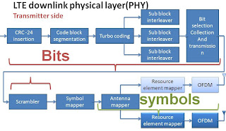
As shown in figure (3.3 and 3.4) the transport block is enter certain number of blocks beginning from the CRC and ending by the OFDM transmitter to be processed to face some of the channel difficulties and to decrease the bit error rate or to increase the bit rate or to provide some of the additional services,And ending with the OFDM transmitter.


Figure 3.1---LTE downlink physical layer. --- Transmitter


Figure 3.2--- LTE downlink physical layer. --- Transmitter


3.1 Difference between Uplink and Downlink


3.1 Difference between Uplink and Downlink:

As shown in figure (3.1 and 3.2) the difference between uplink using SC-FDMA and downlink using FDMA is very small (nearly identical),and it is offer the same degree multipath protection.


Figure 3.1 -----SC-FDMA -----at uplink


Figure 3.2 -----OFDM-----at downlink


It is very clear that the only difference between them the Discrete Fourier transform (DFT) at transmitter and his inverse (IDFT) at receiver at SC-FDMA.

2.5.6 Channel Capacity and Shanon theory


2.5.6 Channel Capacity and Shanon theory:


How fast can we transmit information over a communication channel?

         Suppose a source sends r messages per second, and the entropy of a message is H  bits per message. The information rate is R = r H  bits/second.

One can intuitively reason that, for a given communication system, as the information rate increases the number of errors per second will also increase. Surprisingly, however, this is not the case.

2.5.6.1 Shannon’s theorem:


·        A given communication system has a maximum rate of information C known as the channel capacity.

·        If the information rate R is less than C, then one can approach arbitrarily small error probabilities by using intelligent coding techniques.

·        To get lower error probabilities, the encoder has to work on longer blocks of signal data. This entails longer delays and higher computational requirements.

Thus, if R C then transmission may be accomplished without error in the presence of noise.

Unfortunately, Shannon’s theorem is not a constructive proof,it merely states that such a coding method exists. The proof can therefore not be used to develop a coding method that reaches the channel capacity. The negation of this theorem is also true: if R > C, then errors cannot be avoided regardless of the coding technique used.

2.5.6.2 Shannon-Hartley theorem:


Consider a bandlimited Gaussian channel operating in the presence of additive Gaussian noise:


The Shannon-Hartley theorem states that the channel capacity is given by
where C is the capacity in bits per second , B is the bandwidth of the channel in Hertz, and S /N is the signal-to -noise ratio. 
We cannot prove the theorem, but can partially justify it as follows:Suppose the received signal is accompanied by noise with a RMS voltage of σ , and that the signal has been quantized with levels separated by
.
 If

is chosen sufficiently large, we may expect to be able to recognize the signal level with an acceptable probability of error. Suppose further that each message is to be represented by one voltage level. If there are to be M possible messages, then there must be M levels. The average signal power is then:
                                         

The number of levels for a given average signal power is therefore
Where  is
the noise power. If each message is equally likely , then each carries an equal amount of information
                  

2.5.5 Multi input multi output (MIMO)


2.5.5 Multi input multi output (MIMO):

            MIMO (multiple input, multiple output) is an antenna technology for wireless communications in which multiple antennas are used at both the source (transmitter) and the destination (receiver).
            The antennas at each end of the communications circuit are combined to minimize errors and optimize data speed. MIMO is one of several forms of smart antenna technology, the others being SISO (sungle input single out put) MISO (multiple input, single output) and SIMO (single input, multiple output).
            In conventional wireless communications, a single antenna is used at the source, and another single antenna is used at the destination. In some cases, this gives rise to problems with multipath effects.
            When an electromagnetic field (EM field) is met with obstructions such as hills, canyons, buildings, and utility wires, the wavefronts are scattered, and thus they take many paths to reach the destination.
            The late arrival of scattered portions of the signal causes problems such as fading, cut-out (cliff effect), and intermittent reception (picket fencing). In digital communications systems such as wireless Internet, it can cause a reduction in data speed and an increase in the number of errors.
            The use of two or more antennas, along with the transmission of multiple signals (one for each antenna) at the source and the destination, eliminates the trouble caused by multipath wave propagation, and can even take advantage of this effect.
            MIMO technology has aroused interest because of its possible applications in digital television (DTV), wireless local area networks (WLANs), metropolitan area networks (MANs), and mobile communications.

2.5.4 Orthogonal Frequency-Division Multiple Access (OFDMA)


2.5.4 Orthogonal Frequency-Division Multiple Access (OFDMA):


We can say that’s the main difference between Long Term Evolution (LTE) and other systems.
            And its very similar to Orthogonal frequency Division Multiplexing(OFDM) in function ,with the main difference being that the instead of being allocated all of the available subcarriers ,the base station allocates a subset of carriers to each user in order to accommodate multiple transmissions simultaneously.
            It is Flexibility of deployment across various frequency bands with little needed modification to the air interface, Averaging interferences from neighboring cells, by using different basic carrier permutations between users in different cells. Interferences within the cell are averaged by using allocation with cyclic permutations.
            Enables Single Frequency Network coverage, where coverage problem exists and gives excellent coverage, Offers Frequency diversity by spreading the carriers all over the used spectrum. Allows per channel or per subchannel  power control.
            A Problem with Ofdma as a compared to OFDM is its high sensitivity to frequency offset.
            In OFDM since all the frequencies of the subcarriers were generated by one transmitter, maintaining orthogonality of subcarriers is relatively easy.

            In OFDMA, since many users transmit simultaneously, each with their own estimates of the subcarriers frequencies, a frequency offset is inevitable and multiple access interference occurs as users’ power leaks into subcarriers bands.
            The key difference between both transmission methods is that OFDM allows only one user on the channel at any given time whereas OFDMA allows multiple access on the same channel.

             To enable multiple access subchannelization is used. A subchannel is a group of subcarriers that can be allocated dynamically to different subscribers. Depending on the channel conditions and data requirements modulation and coding is set individually for each subscriber.

            Transmit power can be adapted separately as well, which optimizes the use of network resources. Because of subchannelization OFDMA signals are more complex than OFDM signals and offer better performance and scalability.


2.5.3 Modulation


2.5.3 Modulation:


            Modulation is the process of encoding information from a message source in a manner suitable for transmission. It is generally involves translating a baseband message signal (called the source) to a bandpass signal at frequencies that are very high when compared to the base band frequency.
            The bandpass signal is called the modulated signal, and the baseband message signal is called the modulating signal. Modulation may be done by varying the amplitude, phase or frequency of a high frequency carrier in accordance with the amplitude of the message signal.
            Demodulation is the process of extracting the baseband message from the carrier so that it may be processed by the intended receiver.

2.5.3.1 Analog modulation methods:

1-Amplitude modulation (AM): The amplitude of the carrier signal is varied in accordance to the instantaneous amplitude of the modulating signal.
2-Frequency modulation (FM):The frequency of the carrier signal is varied in accordance to the instantaneous amplitude of the modulating signal.
3-Phase modulation (PM):The phase shift of the carrier signal is varied in accordance to the instantaneous amplitude of the modulating signal.

2.5.3.2 Digital modulation methods:

1-Amplitude-shift keying (ASK):

 The most common ASK form is On-off keying (OOK).

2-Frequency-shift keying (FSK):

  • Binary PSK (BPSK), using M=2 symbols.
  • Quadrature PSK (QPSK), using M=4 symbols.
  • 8PSK, using M=8 symbols.
  • 16PSK, using M=16 symbols.
  • Differential PSK (DPSK).
  • Differential QPSK (DQPSK).
  • Offset QPSK (OQPSK).

 
2011 Mother Reference | Blogger Templates for Over 50 Chat